Theory
Construction of real interferometer
Theory
Displacement measurements with the use of a laser interferometer allow obtaining the accuracy of a displacement measurement of 0.4 ppm in air and 0.02 ppm in vacuum.
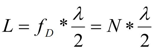
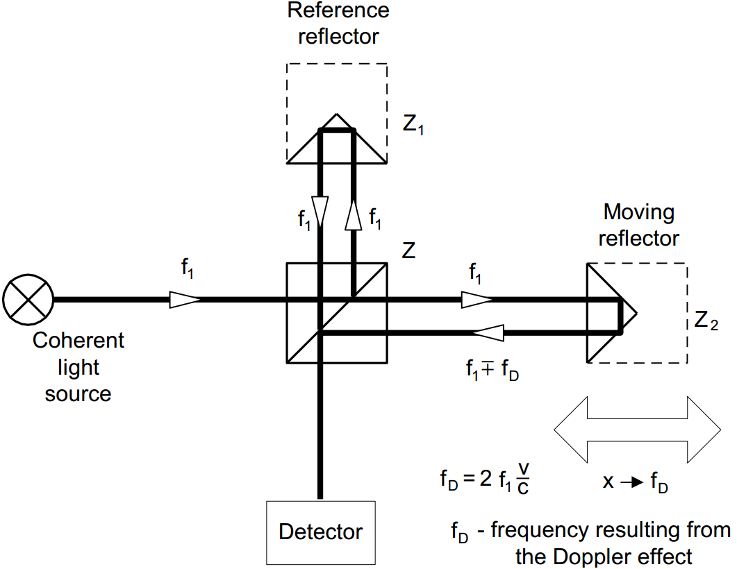
The interferometer was first built by A.A. Michelson in 1881. The simplified schematic of the interferometer is shown in the figure below. Coherent light beam falls on a semi-transparent mirror. This mirror splits the light into two beams. The first goes to the reference arm and reflects from the reflector Z1; the second goes to the measurement arm and reflects form the reflector Z2. The reflected beams meet again on the detector. Because these beams come from the same, coherent, source, they will interfere. When the moving reflector is being displaced, the frequency of the reflected beam in the measurement arm changes. The detector counts the frequency difference between reflected beams – fD. The measured value of the displacement is calculated according to:
Construction of real interferometer
The main disadvantage of Michelson interferometer results from the fact that the detector cannot determine, whether fD is negative or positive thus, from the measurements the displacement of the moving reflector without the sign is obtained.
Currently there are widely used two methods that allow getting also the direction of the movement. Depending on the number of light frequencies (wavelengths) used in the interferometer, the first is called homodyne (one frequency) and the second heterodyne (two frequencies) method.
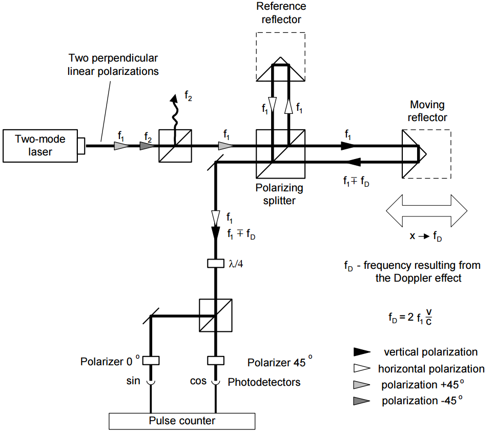
In the homodyne method, shown on figure below, as a coherent source of light a linearly polarized laser is used. If it is two-mode laser (i.e. it generates two wavelengths) than one mode must be cut off with the use of a properly set polarizer. The polarizing splitter splits the light beam from the laser into two beams polarized vertically (90°) and horizontally (0°). The former is directed to the measurement arm and the latter to the reference one. The frequency of the beam in the measurement arm changes with the movement of the moving reflector. The polarization of the reflected beams is changed to circular with the use of a l/4 waveplate. After 0° and 45° polarizers, two signals shifted in phase are obtained. The phase shift is +90° when the measurement arm moves to and -90° when it moves from the laser.
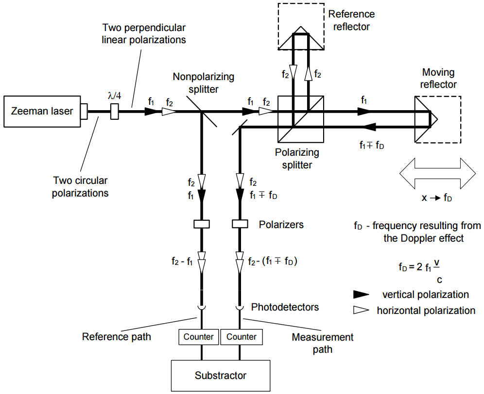
In the heterodyne method, shown on the next figure, two laser frequencies are used. Therefore a two-frequency laser is needed, e.g. a Zeeman laser. A two-mode laser is not suitable for the heterodyne method interferometer, because the difference between f1 and f2 is usually too high for an electronic counter. The output beam of a Zeeman laser consists of two circularly polarized beams, one polarized leftward and the second rightward. A lambda/4 waveplate changes circular polarization to linear.
The main difference between two described methods is that in the heterodyne one the beam frequency in reference arm differs from the beam frequency in the measuring arm. A detection path is also different – subtracting differential frequencies of reference and measuring arms does the measurement.
The heterodyne method gives correct results only when fD does not exceed the difference between the laser frequencies, i.e.: f2 – f1. In reality, that difference, resulting from the Zeeman effect, is about 1MHz. This limits the maximum available velocity of measuring arm, in one direction, to 0.3 m/s. The next disadvantage of the heterodyne method is, that two frequencies must be used for measurements, while in the homodyne method the second may be used for measuring e.g. a second axis.