Because of the encoder type signals available at the Extension Connector EX1 it is possible to use the HPI-3D lite laser encoder integration into a machine control loop. The laser with the linear optics can be used as a very high precision position encoder.

The Cable has on one end the appropriate miniature Hirose connector that should be inserted into the Extension Connector while on the other end there is a standard female three-row DSUB15 connector. The signals available on the DSUB connector are described and can be configured in the HPI Software.
On the output of the HPI-3D there are available two types of encoder outputs: digital (A-Quad-B format, TTL) and analog (SinA/CosB format, 1Vpp). Both types are available at the same time on the Extension Connector and the EX1 cable. The delay between measured movement and output signals is not greater than 10 µs.
Digital output

The digital A-Quad-B signal consists of two digital signals A and B shifted in phase by +90° or -90° depending on the direction of movement. The signals are in 5V CMOS standard and on the connector there are also available negated A and negated B signals – so a differential cable can be used. The maximum frequency of digital output signals (A, B) is limited to 24 MHz.
Analogue output
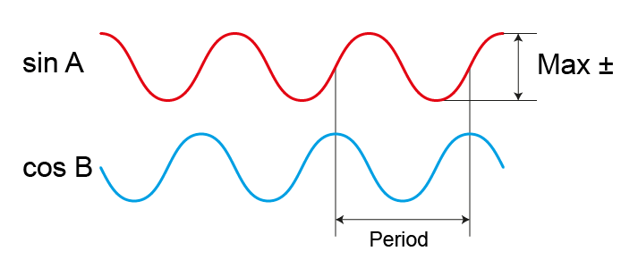
The analog sin A/cos B signal consists of two analog signals sin A and cos B shifted in phase by +90° or -90° depending on the direction of movement. The amplitude of the signals is 1Vpp single ended and 2Vpp differentially. The differential signals are available as a combination of sin A -/sin A and cos B -/cos B signals. The maximum frequency of analog output signals (sinA, cosB) is limited to 2.4 MHz.