Açısal yöntem
Wollaston method
3D method
Açısal yöntem
 Hangi optik kullanılacak?
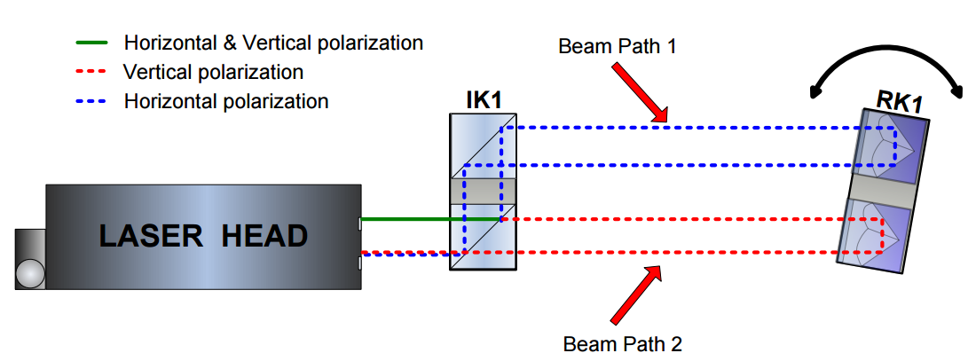
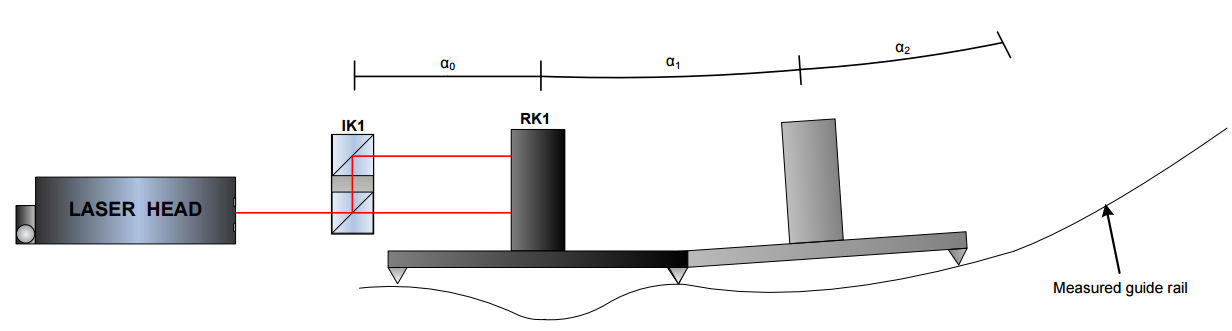
Resimde açısal ölçüm yönteminin uygulamasını görebilirsiniz. HPI-3D’yi açısal optiklerle kullanabilirsiniz. Lazer emitörü iki polarize lazer ışını verir: Yatay (H) ve Dikey (V). Bu mümkündür çünkü IK1 içindeki ışın ayırıcı Brewster açısına ayarlanmıştır. Her iki ışın da ölçüm yoluna yönlendirilir ancak 1” veya 2” mesafe ile paralel olarak kaydırılır (versiyona bağlı olarak).
Ölçüm süreci
Ölçüm işlemi sırasında optik elemanlar arasındaki mesafeyi değiştirirsiniz. Sonuç olarak, her iki ışının frekansı Doppler Etkisine göre değişir. Lazer kafasının yalnızca IK1 ile RK1 arasında bir dönüş olması durumunda bir hareket fark ettiğini unutmayın. Örneğin, ışın yollarının uzunluklarında fark olduğunda. Dönüş açısını (makinenin eğimi veya sapması) veya optik bileşenin dikey hareketini (IK1 veya RK1) elde etmek için ölçülen mesafeyi kullanın.
Açısal optikli lazer kafası doğrusal hareketlere karşı duyarsızdır.
Resim, hesaplama için önemli olan tüm parametrelerle birlikte bir taşıyıcıda bir RK1’i şematik olarak göstermektedir. IK1’in konumunu netleştirmek için referans olarak kabul edilir. Parametrelerin anlamı: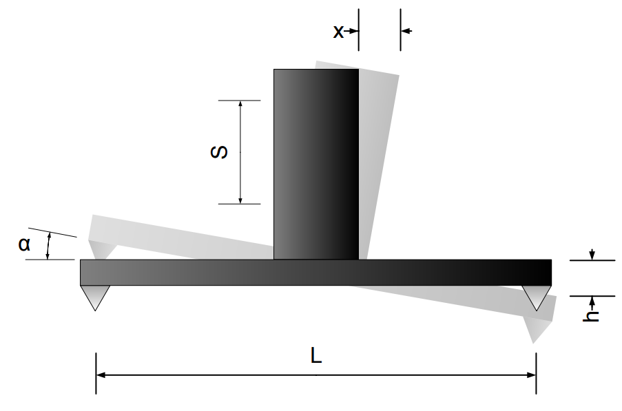
L – Taban uzunluğu;
s – IK1 ve RK1 elemanları üzerindeki ışınlar arasındaki mesafe;
x – Lazer Kafası tarafından ölçülen mesafe;
α – RK1 elemanının açısal dönüşü;
h – iki ölçüm noktası arasındaki yükseklik farkı;
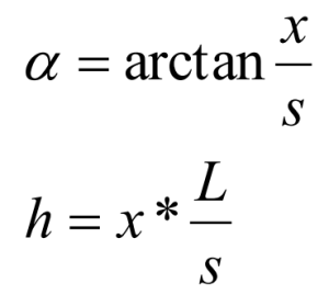
Lazer Kafası x parametresini ölçer. Başka bir deyişle, ışınlar s ve taban uzunluğu L arasındaki mesafe, HPI Yazılımının parametrelerinde ayarlanmalıdır. Ardından yazılım, dönme açısını α ve dikey yöndeki hareketi h hesaplayabilir. Hesaplamalar için formül:
Uygulama Notları
Aşağıdaki ölçüm türleri için açısal optiği kullanın:
Bir makinenin eğim veya sapma ölçümü
Bir makine yatağının düzlüğünün ölçümü
Küçük açıların ölçümü
Bir makinenin eğim veya sapma ölçümü
 İlk iki uygulamanın açıklaması için resme bakınız. RK1 prizma tertibatını bir taşıyıcı üzerinde ölçülen kılavuz ray üzerinde hareket ettirin. Bu arada ölçümleri her 100 mm’de bir gerçekleştirin. Taşıyıcının uzunluğu, daha rahat hale getirmek için genellikle 100 mm’dir. Aynı şekilde, açıları (eğim/yaw ölçümleri için) veya dikey ötelemeleri (doğruluk ölçümleri için) hesaplamak için önceki bölümdeki formülleri kullanın.
Bu tür bir doğruluk ölçüm yönteminin doğru ölçüm noktaları seçimini gerektirdiğini belirtmekte fayda var. Başka bir deyişle, taşıyıcı boyutundan daha yoğun noktaların seçilmesi, aşırı doğrusallık hatalarına neden olur. Ancak hatanın şekli uygundur.
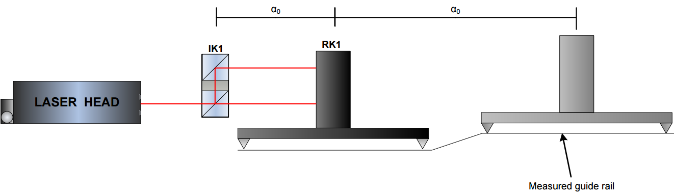
Noktaları çok seyrek seçerseniz, aşağıdaki şekilde gösterildiği gibi hatanın hem şeklini hem de değerini etkileyebilir. Bu özel durumda, ışınlar arasındaki ölçülen mesafe değişmeyecektir, çünkü çok seyrek ölçüm noktaları nedeniyle lazer kılavuz rayın şeklindeki değişikliği fark etmeyecektir!
Küçük açıların ölçümü
Küçük açıların ölçümü, küçük dönüşlerin çok hassas ölçümlerini sağlar. Ancak aşağıdaki iki koşul yerine getirilmelidir:
1. ölçülen açı ±5 derece içinde
2. RK1 ile lazer kafası arasındaki mesafe birkaç santimetreden fazla değişmez.
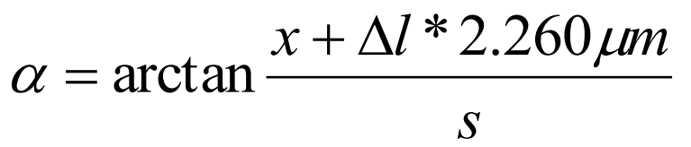 İkinci sınırlama, HPI-3D lazerde bulunan heterodin etkisinden kaynaklanmaktadır. Bu etki açıyı şuna göre etkiler (Δl, ölçümler sırasında lazer ile RK1 arasındaki mesafenin değişmesidir).
Wollaston method
Wollaston optics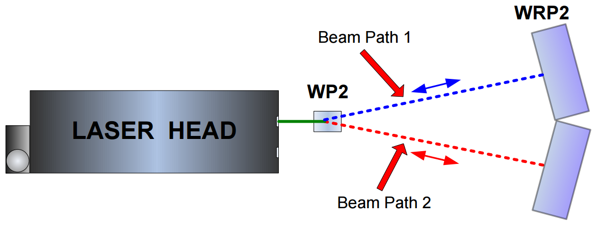
Another way of measuring straightness, parallelism and squareness with the laser interferometer requires the use of Wollaston type optics. The optics consist of two elements: Wollaston polarizing prism WP2 and a paired reflector WRP2 – see figure below. The laser beam, consisting of two perpendicular polarizations, is split by the WP2 element into two beams. The beams are leaving the WP2 at a certain angle and then, after being reflected back by the reflector WRP2 are returning to the laser head. The laser measures the difference between beams’ paths lengths.
Prism construction
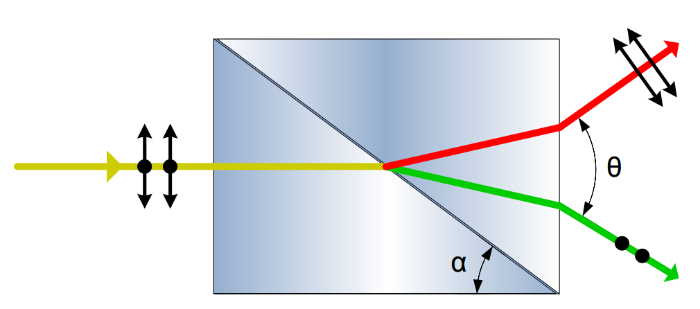
In the figure you can see the the WP2 element operation explanation. This prism is constructed of two birefringent triangle prisms cemented together. Both prisms are built from the same material but their ordinary and extraordinary axes are perpendicular to each other, i.e. refraction coefficient of the ordinary axis of the left prism nol equals to the coefficient value of the extraordinary axis of the right prism ner.
Because of this the orthogonally polarized laser beams entering the Wollaston element are deflected at different angles on the middle boundary layer and on the right boundary layer. This behavior can be easily proven with the use of the Snell’s law. The angle between the exiting beams is often denoted as Θ.
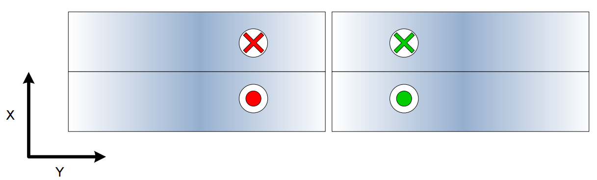 Unlike in the angular optics the distance between beams are changing with distance, thus making the construction of the reflecting element difficult. In the figures below there is shown the construction of the reflection element for the Wollaston optics WRP2. It consists of two special glass prisms glued very precisely at 180-Θ angle. The prisms used in the WRP2 in y axis reflect the beam with ½’’ translation (like the retroreflector RL1). In the x axis the beam is reflected with no translation (like in a mirror).

The laser head with Wollaston optics is sensitive to angular movements of the reflector!
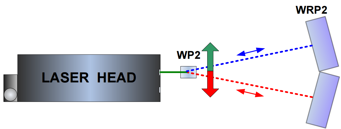 The use of Wollaston optics makes possible the measurement of relative movement of WP2 element in the axis perpendicular to the laser beam. As it is shown in the figure below the measurements are possible ONLY with the WP2 movement.
Because of the sensitivity of the laser readout on the angular movement of the WRP2 it is important that during measurements the WRP2 element is neither touched nor moved.
Application notes
Although it is possible to measure the straightness either with movement of the WP2 or WRP2 element but there are certain differences. The WRP2 this element should be stationary during measurement (i.e. should not be moved along the laser beam). As the WRP2 behaves in one of the axis like a mirror thus any angular movement of the WRP2 in this axis may result in the laser beam not returning to the laser head and will influence significantly the measurement results!
There are no such problems when the WP2 is moved instead. The only disadvantage is the smaller measurement range. WP2 can be moved ±2mm while maximal measurement range of the WRP2 is ±30mm (but only when the distance between WP2and WRP2 is 4.5 m).

3D method
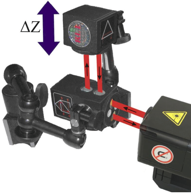
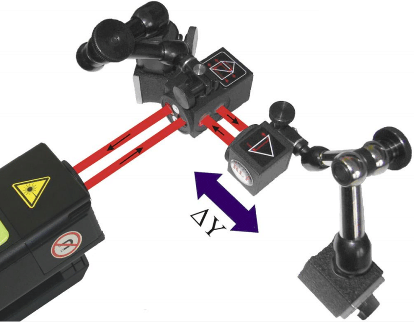
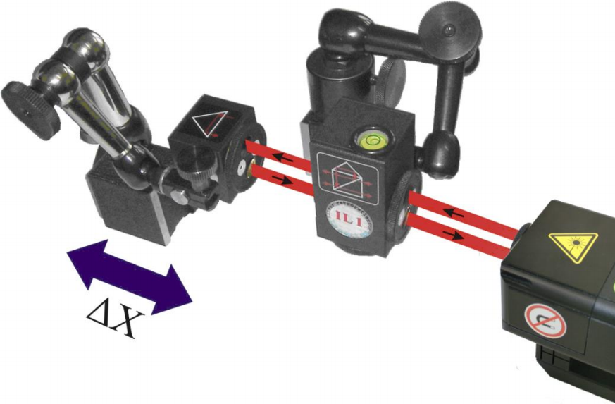
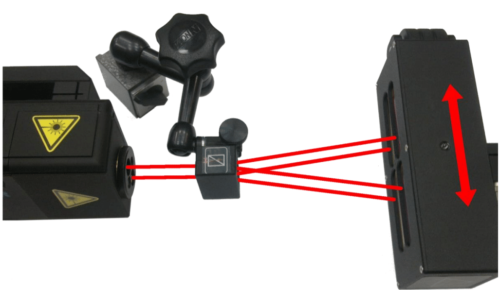
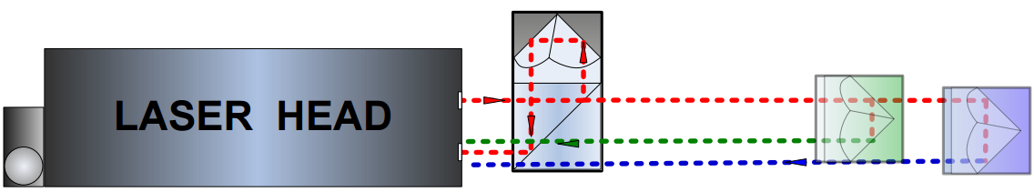 The HPI-3D laser head is capable of detecting the position of the returning beam. The position of the returning beam changes with the movement of the retroreflector RL1 perpendicular to the laser beam axis. This phenomena for one axis is shown in the figure below. The beam returning from the linear interferometer IL1 is treated as a reference while the beam reflected by RL1 as measuring beam. The laser simultaneously registers information about the changes of position of an optical component in both axes perpendicular to the laser beam.
The measured position is then used either for precise control of the laser beam path alignment or for the straightness, squareness or parallelism measurements. The 3D measurement returns absolute values of the beam position. This is different from the main, interferometric measurement axis where obtained results are incremental.
Application notes
The 3D option can be used for rapid estimation of straightness simultaneously in two axes but with some limitations resulting from physical nature of the measurements.
Unlike in all interferometric measurements, the laser head takes active part in the measurements, i.e. its position and its vibrations influences the measurement results. For this reason it is important to avoid using the tripod stand and to fix the laser head directly on the measured machine.
The 3D measurement bases on the position of the returning beam on the position sensitive device. Thus it is important that the beam stays within the measurement range of the device, i.e. ±1 mm. Using 3D option outside this range would produce unreliable results.
Similarly to all laser based straightness measurements the air turbulences have an influence on the results. Small wandering of the laser beam can be accommodated by the signal processing circuit inside the laser with the change of averaging time (see Software Description for more details). If the air movements are too large – i.e. when the beam returning to the laser wanders outside ±1 mm window – then the results of the 3D measurements may become unusable. In such situation either some shielding from the air movement or a fan forcing the air movement have to be used. The problem with air turbulences is more troublesome for larger distances between the laser head and RL1 element.